
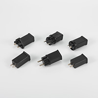
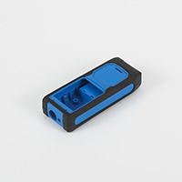
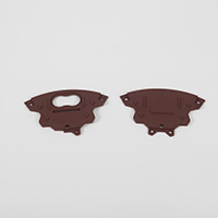
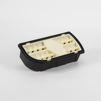
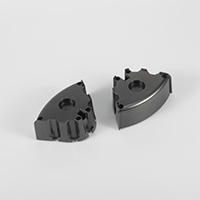
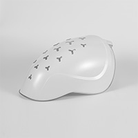



Injection molding is a widely adopted manufacturing process that allows for the efficient production of plastic parts with intricate designs. To ensure successful outcomes, it's important to consider several aspects of injection molding design. There are several key factors that play a crucial role in the design process, including material options, parting lines, tolerances, sink marks, wall thickness, gate designs, gate location, shut-off angles, draft angle orientation, texturing, and draft. Understanding these elements will help you optimize your design for manufacturability and enhance the overall quality of your injection molded parts.
- Material Options and ConsequencesChoosing the right material is essential in injection molding design. Consider factors such as material properties, intended application, durability, and cost. Different materials may have varying melt temperatures, shrinkage rates, flow properties, and mechanical characteristics, which can affect the overall design and part performance. Collaborating with material suppliers and conducting material testing will help you make an informed decision.

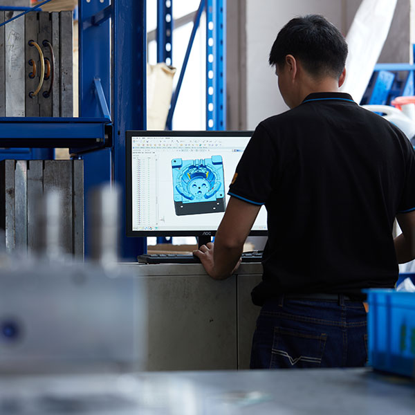
- DFM AnalysisWhile most manufacturers won’t provide manufacturability feedback until after the order is purchased, MOUETTE will provide full DFM analysis for free with your quote. The aim at this stage is to learn all the potential issues or risks for tool manufacturing and injection molding. Then, you’ll need to improve or resolve any issues by updating the CAD design and parts 3D design to avoid future tooling modification. This stage is critical because when the part is in the design stage, most small modifications only take half an hour or a few minutes to complete, but when the tooling is done, it takes at least a few days and hundreds of dollars to make even a small tooling modification.
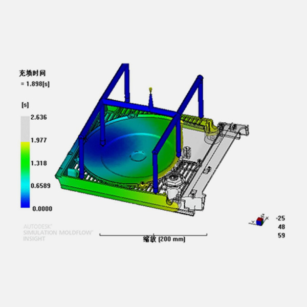
At this stage, MOUETTE will also inform you as to how the tooling and injection molding will affect your plastic parts.
Considerations Include:
● The type of gate ( edge gate, sub-gate, hot tip gate or sprue gate?)
● The location of the gate (the gate shouldn’t scar the cosmetic surface).
● The location of the parting line and split line (are they acceptable from an aesthetic viewpoint?)
● The location of the ejection mark (they should be on the inside and shouldn’t affect the function by being on the sliding track).
● Tthe location of the knit line (the line where two flow fronts meet) and what it will look like.● Additional risks, like Sink marks, tolerance and deformation.
Design Verification
After improving or resolving the issues mentioned by DFM, and updating the CAD design and parts 3D design, verify your design with 3D printed, CNC machined, or urethane cast prototypes to test if the plastic part meets the requirements for function, strength, aesthetics, and durability.Selecting a Parting Line
The parting line is the boundary where two halves of the mold meet. Careful consideration should be given to selecting an appropriate parting line location to ensure optimal mold functionality and ease of part ejection. The parting line, where the mold opens and closes, determines the direction of your draft. Avoiding complex parting lines whenever possible simplifies the mold design and reduces manufacturing costs.Critical Tolerances
Tolerances define the acceptable deviation from the desired dimensions of a part. Identify critical dimensions that require tight tolerances and communicate them clearly with the mold designer and manufacturer. Consider the material shrinkage, part geometry, and the capabilities of the injection molding process when establishing tolerances to ensure functional and accurate parts.Sink Marks
Sink marks occur when uneven cooling or shrinkage of thick sections in a part creates depressions on the surface. To minimize sink marks, ensure uniform wall thickness throughout the part, avoid abrupt changes in wall thickness, and optimize the gate and cooling system design. Sink marks can impact the aesthetic appeal and structural integrity of the final part.
Experienced designers are always faced with the challenge of avoiding sink marks in injection molded parts. Although the recommended maximum wall thickness at the base of a rib or boss should be less than 60% that of the perpendicular face wall, some molders prefer 50% or less. It should be noted that this is a guideline and not a guarantee that the part will be acceptable to the QC department.
Avoiding sink marks on cosmetic surfaces is always a challenge during the design development of injection molded parts. MOUETTE will do moldflow analysis, and list the sink marks area of the parts, and give some optimization suggestions.Wall Thickness
Maintaining uniform wall thickness is crucial to achieve consistent part quality and avoid defects. Uneven wall thickness can lead to filling imbalances, warpage, and sink marks. Design parts with a consistent wall thickness, but also consider material flow and structural requirements. Ribbing or gussets can be used to reinforce thin walls.If sections of different thickness are required, make the transition as smooth as possible allowing the material to flow more evenly inside the cavity. This ensures the whole mold will be fully filled and will ultimately decrease the chance for defects. Rounding or tapering thickness transitions will minimize molded-in stresses and stress concentration associated with abrupt changes in thickness.
Incorporating the proper wall thickness for your part can have drastic effects on the cost and production speed of manufacturing. The minimum wall thickness that can be used depends on the size and geometry of the part, structural requirements, and flow behavior of the resin. The wall thicknesses of an injection molded part generally range from 2mm – 4mm (0.080" – 0.160"). Thin wall injection molding can produce walls as thin as 0.5mm (0.020"). MOUETTE is an experienced injection molder, we always help customers to find a suitable solution of wall thicknesses are executed for the part’s design and material selection.
- Common Gate DesignsGates are the entry points through which molten plastic material is injected into the mold cavity. Common gate designs include the edge gate, sub-gate, hot tip gate and sprue gate. Each gate design has its advantages and disadvantages in terms of part appearance, mold complexity, and ease of processing. Consider the specific requirements of your part and consult with the mold designer to select the appropriate gate design.
Edge Gates Edge gates are best suited for flat parts, and, as the name implies, located at the edge. This type of gate will create a scar on the parting line.
Sub-gates
Sub-gates are common but require ejector pins to automatically trim. These types of gates have different variations, such as banana gates, smiley gates, and tunnel gates. These allow you to move the gate away from the parting line, which is useful when your gate location needs to be moved away from the parting line to enhance filling.Hot Tip Gates
Hot tip gates are located at the top of the mold, typically only in locations where the geometry is round or conical. These type of gates are also only used with hot runner injection molds.Sprue Gates
Direct or sprue gates are used for single-cavity molds that are typically large and cylindrical. These are the easiest of the mentioned gates to manufacture and maintain and are also low-cost. Although these are the most simple of gates, they leave a large scar at their point of contact.- Gate LocationGate location is critical for achieving proper material flow and minimizing part defects. It should be strategically placed to ensure even filling, minimize weld lines, and reduce part warpage. Gate location can also affect the appearance of the part. Factors such as part geometry, material flow characteristics, and aesthetic requirements influence gate placement decisions.
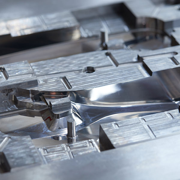
To avoid issues arising from your gate location, here are a few guidelines on proper gate location(s):
● Place gates at the heaviest cross section to allow for part packing and minimize voids and sink.
● Minimize obstructions in the flow path by placing gates away from cores and pins. Be sure that stress from the gate is in an area that will not affect part function or aesthetics.
● If you are using a plastic with a high shrink grade, the part may shrink near the gate causing "gate pucker" if there is high molded-in stress at the gate.
● Be sure to allow for easy manual or automatic degating.
● Gate should minimize flow path length to avoid cosmetic flow marks.
● In some cases, it may be necessary to add a second gate to properly fill the parts.
● If filling problems occur with thinly walled parts, add flow channels or make wall thickness adjustments to correct the flow.
Gates vary in size and shape depending upon the type of plastic being molded and the size of the part. Large parts will require larger gates to provide a bigger flow of resin to shorten the mold time. Small gates have a better appearance but take longer to mold or require higher pressure to fill correctly.
Shut-off Angles
Shut-off angles are the angles incorporated into the mold design to facilitate the removal of the part from the mold. They help prevent damage to the part and the mold during ejection. Consider draft angles and appropriate shut-off angles to ensure smooth ejection and avoid part deformation or sticking.Draft Angle Orientation
When we begin detailing a concept and transforming it into a production injection molded part, draft angles must be added to all surfaces in line of draw. In most cases the draft orientation is obvious. However, there are instances where the draft can be oriented toward the core or cavity. These decisions affect parting lines, tool design, fits between parts and cost. There are instances where the location of the parting line could unnecessarily complicate the mold and increase tooling cost. Reviewing these details with the injection molder during the development process will ensure that the design has been optimized for minimal cost and optimal performance when it is transferred to the molder for production.- FinishingSurface finish options for plastic injection molded parts vary depending on part design and the chemical make-up of the material used. Finishing options should be discussed early in the design process as the material chosen may have a significant impact on the type of finish implemented. In the case where a gloss finish is used, material selection may be especially important.
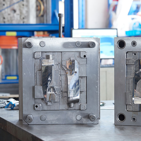
Basic Surface Finish
The surface of the plastic part is a direct translation of the surface of the mold. For example, to mold a clear lens, the mold will have a highly polished or mirrored surface. In these cases, even a fingerprint or a hairline scratch can show through on the molded part. Figure 1 is a surface finish guide created by the Plastic Industry Association for use during plastic injection molding.Mold Finish Guide
A-1
Grade #3 Diamond Buff
A-2
Grade #6 Diamond Buff
A-3
Grade #15 Diamond Buff
B-1
600 Grit Paper
B-2
400 Grit Paper
B-3
320 Grit Paper
C-1
600 Stone
C-2
400 Stone
C-3
320 Stone
As you can imagine, going up the scale to the “A” surface finish gets more time consuming, and therefore, raises tooling cost. Starting at C-3, each stage on this scale builds on the one before it. That is, you would not start with diamond polish on a surface with tooling marks. You would work your way up the scale through the different finishes.
Textures
Texturing is a process used to apply patterns to a mold surface. This process allows flexibility in creating the final appearance of your parts. Texturing is an integral piece in overall product development and should be considered during the design process to achieve the desired results. Texture can be a functional component of design (for example, to improve grip), as well as a strategy for camouflaging imperfect or frequently handled parts. Texture can also be used to reduce part wear from friction.A wide variety of textures are available for injection molded parts such as:
● Natural
● Matte Finishes
● Multi-Gloss Patterns
● Graphics
When applying a texture to a part, the 3D parts drawing must be adjusted to accommodate for this surface variance. If the texture is on a surface that is perpendicular or angled away from the mold opening, then no draft changes are necessary. If the texture is on a parallel surface with the mold opening, however, increased draft is necessary to prevent scraping and drag marks that could occur during part ejection. Different textures have different impacts on the molded part. The rule-of-thumb when designing for texture is to have 1.5 degrees of draft for each 0.001" of texture finish depth.
Whether you have a new part, are updating an existing one, or changing the manufacturing process, it’s important to design for manufacturing. The short and long-term cost/timing implications can be large if you’re not designing a component with the manufacturing process in mind.
If you’re designing a plastic part, we highly recommend getting an experienced injection molder like MOUETTE involved as early as possible. With MOUETTE, you can leverage years of experience, a network of suppliers, in-house injection mold design, mold building, and injection molding to make your product come to life quickly and efficiently.
The next step is to upload your 3D CAD model online where you'll receive an interactive quote with free DFM analysis within hours. As we said earlier, the DFM analysis will highlight any moldabilty issues and even suggest solutions. We recommend pairing that design feedback with a conversation with one of our experienced applications engineers who will help with any further guidance you might need before production begins.



Integrity, And Responsiveness.














 ISO 9001 - 2015
Our Specialties.


Get Started With Your Next Injection Molding Project.
If you have any questions about our products and services, please do not hesitate to contact us. Our team will reach you within 12 hours!
We offer an expansive selection of customization options that match the unique demands of the OEM market.
Quality control is always the highest priority, upholding strict standards in every step of the manufacturing process.